Metrological aspects in the metal magnetic memory method
Dr., Professor A.A. Dubov
Nowadays the metal magnetic memory (MMM) method is becoming increasingly widespread in practical application for equipment and structures diagnostics in Russia and other countries. Article [1] presents fundamental differences between the MMM method and other magnetic NDT methods. The physical bases of the MMM method are considered in papers [2 - 4]. Russian and international standards on the MMM method [5 - 7] are available.
In accordance with GOST R ISO 24497-1-2009 [5], the MMM method is a non-destructive testing method based on recording and analyzing the distribution of self-magnetic stray fields (SMSF) that occur on products and equipment in stress concentration zones (SCZs).
SCZs are not only the areas known ahead, where the structure features create various conditions for distribution of stresses due to external work load, but these are randomly located areas where large strains (as a rule, shear strains) occurred due to initial inhomogeneity of the metal structure combined with off-design additional work loads.
Inspection by the MMM method is carried out without metal dressing or artificial magnetization. The method uses the residual magnetization, which formed naturally during components fabrication and in the course of their operation.
Melting, forging, presswork, heat treatment and welding are performed at a temperature much higher than the Curie point of the metal (for iron-based alloys it is of the order of 760-770°C), when the residual magnetization disappears.
During subsequent metal cooling at the time of passing through the Curie point (Tc), when the magnetic permeability µ is maximal, the components achieve high level of thermoremanent magnetization even in a weak external geomagnetic field.
As a result of this process, during which the energy of crystallization and thermal stresses (external layers of the component cool faster than internal ones) is an order of magnitude greater than that of the weak external magnetic field, the distribution of thermoremanent magnetization in components by size and direction is determined by the component shape, its structural and process inhomogeneity. Thus, the metal's structural and technological history, conditioned by the cooling process, manifests itself in the form of natural magnetization (magnetic memory of metal).
Numerous studies carried out by the method developers at manufacturing plants have shown that practically all same-type components made of the same steel grade and under the same technology have identical distribution of residual magnetization, and magnetic anomalies are recorded during the inspection on individual components only in zones of residual stress concentration and various structural inhomogeneities [8].
In conditions of operation under the effect of workloads, the thermoremanent magnetization is redistributed, and in SCZs there occur magnetic anomalies that are recorded in the express control mode using specialized scanning devices and magnetometric instruments.
Magnetometric instruments "TSC" (Testers of Stress Concentration), used in the metal magnetic memory method for SCZs detection, are certified and provided with the Pattern Approval Certificate of Measuring Equipment of the Federal Agency for Technical Regulation and Metrology. The instruments measure the magnetic field intensity in A/m, and the results of these measurements are converted using special techniques into diagnostic parameters characterizing the state of the inspection object (IO). The instruments are annually calibrated using a standardizing instrument verified in accordance with the established procedure.
Inspection of engineering products and various equipment by the MMM method is carried out using the instruments with specialized sensors by means of scanning along the component's surface with recording the SMSF variation.
One should note a very important feature of the SMSF in the MMM method - reflecting the internal rheological properties of components' material: force-torque stresses, reaction to the effect of external forces and relaxation simultaneously with geometric displacements during deformation [9].
The geometric feature of magnetic anomalies in the distribution of SMSFs, characterizing SCZs, is the distance between the extreme values of the self-magnetic field divisible by the component's standard size (thickness, width, diameter).
Special geometric features of the SMSF, recorded in SCZs, are a very important metrological factor in the MMM method. This factor makes allows during practical diagnostics to separate the useful magnetic signal from the false one.
The MMM method can be used on components made of ferro- and paramagnetic materials. For each specific component (or a unit within the structure) of the same standard size, made of the same material, a separate inspection procedure is developed.
Taking into account that the main task of the MMM method is to detect SCZs, which are sources of all types of damage (corrosion, fatigue, creep), the diagnostic parameters have been developed to solve this problem.
For quantitative assessment of the level of stress concentration (sources of damage) during scanning along the IO surface, the gradient of the normal (Нy) and/or tangential (Нх) SMSF component is determined:
K = |ΔН| / Δx, at Δx→0 K = dН / dx, (1)
where Δx - is the distance between the adjacent points of inspection.
In some cases, during the equipment's stress-strain state (SSS) control the resulting SMSF is used, which is calculated based on the results of measuring the three components

and the gradient |ΔН| / Δx.
Among the basic design diagnostic parameters, the MMM method uses the parameter m, which characterizes the limiting strain capacity of the material:
m = Кmax / Кave, (2)
where Кmax and Кave, are, respectively, maximum and average field gradient values, which are determined during the inspection by the MMM method of the same-type of equipment units.
In the course of industrial and laboratory studies on specimens, the ratio between the limiting values of the magnetic and mechanical parameters was established:
mlim = Кmax / Кave ≈ Кlim / Кt ≈ σlim / σt, (3)
where Кmax and Кave values, obtained as a result of inspection of the same-type of equipment units, correspond to the Кlim and Кt values, obtained as a result of tensile testing of specimens made of the same steel grade when achieving, respectively, the true tensile limit strength σlim and the conditional ultimate strength σt.
In experimental studies, it was also found that if the actual parameter mact ≥ mlim, then in this case the limiting (critical) state occurs in the metal of the inspected equipment unit, at which a macrocrack forms. The physical substantiation of mlim parameter is provided in papers [3, 10].
The ratio (3) can be illustrated on the example of the results of a steel specimen tensile testing with constant strain rate up to its rupture with simultaneous measurement of the specimen's SMSF by the MPM method.
Figure 1 presents the σ-ε diagram combined with the total SMSF increment graph Ʃ|∆Н| obtained during steel specimen tensile strain.
Let us calculate using this example the value of the parameter m by the ratio (3) between the magnetic and mechanical characteristics.
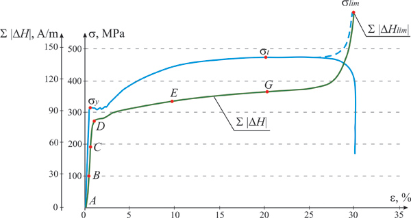
On the σ-ε diagram section from the point corresponding to the ultimate strength σt to the point corresponding to σlim, the dashed line shows variation of true stress relative to the changing section in the specimen neck up to the limiting (failure) stress. Figure 1 below shows the curve of specimen's SMSF increments Σ|∆Н|=ƒ(ε) corresponding to σ-ε diagram. For this specimen the value σtrecorded on the tensile machine diagram is 470 MPa, and the design stress σlim relative to the cross-sectional area in the neck turned out to be 990 MPa.
Then the value of mlim parameter for mechanical characteristics will be equal to:
mlim = σlim / σt = 990MPa / 470MPa = 2,11, (4)
and the value of mlim parameter for magnetic increments is equal to:
mlim = Ʃ|∆Нlim| / Ʃ|∆Нt| = 214 / 106 = 2,02, (5)
where Ʃ|∆Нt| and Ʃ|∆Нlim| - of SMSF modular values obtained when achieving the conditional ultimate strength σt and the true tensile limit strength σlim, respectively.
Thus, as a result of this steel specimen tensile testing, a good confirmation of the ratio (3) between the magnetic and mechanical characteristics was obtained. Similar confirmation of the ratio (3) was obtained repeatedly, when testing steel specimens made of materials with a cubic lattice.
The MMM method uses the ratio (3) to estimate the metal's limiting state of a real equipment, in which the main macrocrack is formed in the SCZ, and the damage development begins.
The diagnostic parameter m in the MMM method is a very important parameter in terms of metrology, since it allows determining the limiting state of the metal in the SCZ and the time of cracking initiation.
For example, in the acoustic emission (AE) method estimation of the cracking process initiation is still a problem during the equipment inspection [11].
Here it should be noted that opening of macrocracks, when the metal reaches its limiting state, makes fractions of millimeters, which is a dead zone for most NDT methods. In this connection, one should also note a very important feature of the MMM method consisting in the fact that it allows assessing the degree of their hazard and drawing conclusions about the direction and intensity of their development by the parameters of magnetic anomalies in the SCZs, where macrocracks have already occurred.
Let us further consider in more detail the capabilities of the MMM method in solving the above problem in terms of metrological support. As it was noted earlier, the MMM method is primarily a method of the actual stress-strain state (SSS) control, whose main task is to detect a SCZ with the geometric features of SMSF distribution in this zone, conditioned by the standard size of this IO. The MMM method uses a "standardless" method of SSS control, i.e. by comparing the magnetic anomalies by SMSF amplitude and width in the SCZ and outside this zone. This comparison is performed individually for each IO. However, the energy ratio between the magnetic and mechanical parameters (3) for different IOs of different standard sizes but made of the same material, is the same. This regularity was established both in laboratory tests (Figure 1) and in numerous practical works. The ratio (3) allows solving the "scale factor" problem when transferring the calibration dependencies obtained on the specimens to the actual equipment.
One of the experimentally established and used in the MMM techniques dependencies is approximation of the objectively existing interrelation of limiting strain parameters in the local area of the developing damage with average statistical strain-force macro characteristics of the material, obtained during testing of specimens [3, 4].
At the same time, it is of fundamental importance that the stray field over the anomalous area is formed not by any one kind of local strain, but by the set of all types of local strain that takes into account not only their absolute values but also the orientation ratios in the force field space – the set that determines the local density of the material's proper energy changed under the external effect. This is the fundamental difference between the method of magnetic memory and all other methods of SSS diagnostics.
The revealed magnetomechanical criterion for the material's limiting state assessment - the ratio of the limiting value of the material's internal energy density to the average value - required "translation" into the familiar "language" when it was used in practice. This "translation", proposed by the author of the MMM method, is expressed by a simple function:
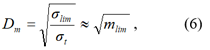
where Dm - is coefficient calculated by the measured stray field parameters determined by the set of local strains in the area of the occurred macrocrack, the equivalent of which, as can now be understood from the results obtained above, is the average relative longitudinal strain (εnon-uni) in the area of non-uniform strain (in the "neck" area) i.e. Dm = εnon-uni. This coefficient is called the "limiting stress concentration factor".
Figure 2, a shows the distribution of the range of square root values calculated from the ratio of the specific load limit value to the ultimate strength limit for different materials (Table 1) depending on appropriate relative elongation average values in the area of non-uniform strain of the specimen [3]. The same Figure 2, a shows two functions: the one obtained by calculation for all 98 tested specimens and the "exact approximation" - the dashed line, and the function of "translation" (6) used in the diagnostic techniques by the MMM method - the solid line.
Figure 2, b shows the distribution of approximation errors of the revealed regularity in paper [3] with the function of "translation".
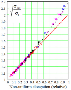
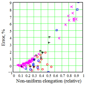
Figure.2. One of the main dependencies used in the MMM method for SSS assessment of different materials (solid line) (a), and the potential MMM error (b).
Table 1.
| N | Alloy type | Specimen group characteristics | Designation on the graph | Number of specimens |
|---|---|---|---|---|
Test results |
||||
| 1. | Titanium alloy | the same grade | × - I | 22 |
| 2. | Rail steel | the same grade | × - II | 27 |
| 3. | Aluminium alloy | the same grade | × - III | 12 |
Reference data |
||||
| 4. | Ferromagnetic carbon steels | different grades | ○ | 13 |
| 5. | Chromium low- and medium-alloy steels | different grades | □ | 12 |
| 6. | Chromium-nickel alloys | different grades | + | 12 |
Total number of specimens and grades |
98 |
|||
Table 2 shows the statistics of the considered error distribution for steel groups indicated in Table 1. In fact, this is the potential reliability1) statistics of the values of the "limiting stress concentration factor" used in the diagnostic techniques by the MMM method.
1) Potential reliability is the maximum possible reliability of results determined by the method ideology, i.e., the adequacy of the used approximating functions to the actual physical regularities of the studied process.
As it can be seen from Table 2, the reliability of diagnostic results and material's state assessment is sufficiently high when the MMM method is used (at least 90%).
Table 2. Statistical characteristics of potential values reliability of the "limiting stress concentration factor" used in the MMM method
| Scatter parameters | Number of the studied alloy group | For all groups | |||
|---|---|---|---|---|---|
| 1, 2, 3 | 4 | 5 | 6 | ||
| Maximum deviations, % | -1,1 9,1 |
||||
| Average deviation, % | 1,5 | 0,3 | 1,8 | 1,4 | 1,4 |
| Mean square deviation, % | 2,5 | 0,9 | 3,4 | 1,3 | 2,4 |
It should be noted that configuration of the self-magnetic stray field induction flux in the local area of the metal with anomalous strain values on the specimen's or diagnosed object's surface is inhomogeneous.
SMSF induction flux due to glide strain has the form of an open sheaf, and the induction vector "sheaf" width on the object's surface is determined by the local area dimensions only. Simple logic shows that to achieve maximum resolution, determined by the size of the local area, it is necessary to reduce the diameter of the receiving inductance "coil".
Note that in this case nothing, except for merely structural capabilities, limits the minimum size of the receiver. However, besides structural and technical difficulties in manufacturing small diameter receivers, there is a "common sense" based on numerous experimental results stating that there is no need to "infinitely" reduce the receiver diameter: even at a diameter of 1 mm, an optimal resolution of not more than 10÷50 μm is realized, which allows recording of local anomalies, in which the material's state is still very far from failure development. No one of the known non-destructive methods of materials' stress-strain state diagnostics possesses such high resolution.
Metrological boundary conditions
Based on the experience of the MMM method and appropriate inspection instruments application, errors were identified that are referred to metrological boundary conditions. These errors are conditionally divided into the following groups:
- errors occurring during SMSF measurements on the inspection object, depending on the sensor type and its position relative to the surface;
- errors related to offsetting from the demagnetizing factor effect;
- errors related to artificial magnetization from external sources;
- errors conditioned by the inspection object's external surface condition (presence of insulation, paint, scale, etc.);
- errors that depend on adjustment and calibration of inspection instruments and internal instrumental "noise" caused by the processor and microchips operation;
- random errors due to cold work, friction of contacting parts, etc.
In conclusion, it is necessary to note the following. The MMM method metrological support considered in this article covers the field of engineering products' and equipment SSS control before the metal reaches its limiting state (up to the time of cracking) in local SCZs. For solution of this problem, the listed boundary conditions do not have a significant effect when determining the design parameter m that characterizes the metal’s state in the SCZs, as this parameter is relative to background values of SMSF on IO. Very important boundary conditions that must be taken into account when assessing the state of components or units in a structure are: similarity of shape and standard size, fabrication technology, steel grade (structural and mechanical properties of the metal), the same location during components or units inspection relative to the external geomagnetic field, the same design and operating parameters. The listed boundary conditions must be fulfilled for the determination of homogeneous rheological fields [9] (in the MMM method - this is SMSF).
Metrological boundary conditions have a more significant effect at classification of SMSF parameters by types and sizes of developed defects after exceeding the metal's limiting state in the SCZ. These conditions are discussed in more detail in special techniques. Currently the problem of classification by defect types and sizes, as a rule, is solved during the integrated inspection by means of combination of the MMM method with other NDT methods. The MMM method in the express control mode determines SCZs - sources of developing defects, and then additional control is carried out in these zones, for example, UT with the defects classification in accordance with the UT standards. With such an integrated approach, inspection is greatly simplified and at the same time its efficiency is increased.
References
1. A.A. Dubov. Fundamental features distinguishing the metal magnetic memory method from other known magnetic non-destructive testing methods. Totals and prospects of the method development // Territory NDT, 2016, No. 2. pp. 64-68.
2. V.T. Vlasov, A.A. Dubov. Physical bases of the metal magnetic memory method. Moscow: ZAO "Tisso", 2004. 424 p.
3. V.T. Vlasov, A.A. Dubov. Physical theory of the "strain-failure" process. Part I. Physical criteria of metal's limiting states. Moscow: ZAO "Tisso", 2007. 517 p.
4. V.T. Vlasov, A.A. Dubov. Physical theory of the "strain-failure" process. Part II. Process thermodynamics. Moscow: "Spektr" Publishing House, 2016. 228 p.
5. ISO 24497-1:2007(E). Non-destructive testing - Metal magnetic memory - Part 1: Vocabulary.
6. ISO 24497-2:2007(E). Non-destructive testing – Metal magnetic memory – Part 2: General requirements.
7. ISO 24497-3:2007(E). Non-destructive testing - Metal magnetic memory - Part 3: Inspection of welded joints.
8. A.A. Dubov. Detection of metallurgical and process defects in engineering products using the magnetic memory of metal // Metallurgist, 2015, No. 2. pp. 62-65.
9. T.Ya. Gorazdovsky. Scientific bases of rheology. Lugansk: All Ukrainian National University, 2009. 699 p.
10. A.A. Dubov, Al.A. Dubov, S.M. Kolokolnikov. Metal magnetic memory method and inspection instruments: Training Handbook. Fifth edition. Moscow: "Spektr" Publishing House, 2012. 395 p.
11. V.N. Ovcharuk. Metrological aspects of recording of materials acoustic emission energy parameters // Izmeritelnaya tekhnika, 2014, No. 8. pp. 57-61.