Inspection of equipment' and structures' stress-strain state during the residual lifetime assessment on the objects of industry and transport
Modern diagnostics of structural materials' state, possessing the large arsenal of various physical methods and means, is not already limited by flaw detection tasks and is more and more widely used for solution of the tasks of the materials' mechanical characteristics determination. And methods and means of residual and working internal stresses measurement occupy the major place here.
In connection with this methods of engineering diagnostics, combining the fracture mechanics, physical metallurgy and non-destructive testing, come to the forefront. Methods of stress-strain state (SSS) assessment are primarily referred to such methods.
All leading diagnostic centers of the world are occupied nowadays by the problem of mechanical stresses measurement in operating structures in order to assess their state. However, till date the effectiveness of various methods and means for stress control remains low at their application directly on metal components.
The analysis of capabilities of the known stresses and strains control methods and means in the base metal and welded joints of metal components and structures allows naming the following their sufficient drawbacks:
- unsuitability for inspection of long pipelines and structures, large-sized products, metal components and vessels;
- impossibility to use most of the methods in the plastic strain area;
- variation of the metal structure is not considered;
- impossibility to assess the depth layers of the metal for most inspection methods;
- the need to make graduated diagrams based on the preliminarily prepared samples, which, as a rule, do not reflect the actual energy state of metal components;
- the need for inspection surface and inspection objects preparation (dressing, active magnetization, sensors adhesion, etc.);
- complexity of testing sensors location determination related to the direction of the action of maximum stresses and strains, determining the structure reliability.
Besides, the traditional methods and means of stress NDT, based on active interaction of the instrument signal with the structure’s metal, obtain indirect information on the stressed state of the inspection object, i.e. they have insufficient self-descriptiveness of physical fields used at inspection. Indeed, the field introduced in the investigated material, while interacting with self-magnetic fields of the material, changes its properties and the inspection object’s SSS characteristics. The nature, amount and lifetime of changes are determined by the dynamic ratio of the energies of the interacting fields. In practice such changes are simply neglected during carrying out the diagnostics.
This note refers, first of all, to the following methods:
- the coercive force method (various modifications of coercive force meters);
- the magnetic anisotropy method (the Complex 2.05 and 2.06 Type instruments);
- the methods using the Barkhausen effect (the Stresscan, Intromat, Pion and other Type instruments).
It should be kept in mind that any physical field introduced artificially from the instrument in the inspection object, being in a stress-strain state (even after working loads relief), will by all means interact with the material's proper physical fields (for example, electromagnetic) formed at the lattice level. Neglecting the actual energy state of inspection object (for example, the "magnetic memory of the metal" indicates this) is a gross mistake for all methods of SSS inspection! It especially concerns stress concentration zones (SCZs) concentrated, as a rule, at the depth and in the volume, and coming to the product's surface in the form of glide lines (sites of cracks formation!) with the width of several microns (and even of several submicrons!). Besides, inspection is carried out, as a rule, on equipment shut down for repairs after working loads relief in conditions of the residual SSS, when stresses and strains have opposite signs and different values as compared to the working ones. In these objective conditions the above-mentioned inspection methods turn out to be ineffective for the inspection object's actual SSS assessment both by their physics and by the metrological conditions (instrument sensors, as a rule, are sufficiently larger than the area of SCZs), and what is important - it is not known, to what depth the metal should be artificially magnetized, where and how to install the sensor, when zones of maximum stresses (working or residual) are unknown.
Thus, the above-listed drawbacks of the well-known methods of SSS inspection are conditioned by these methods' physics and are regular. The lack of the metrological basis for materials' SSS characteristics measuring means certification and calibration (till date there are no unified standards and samples in Russia and other countries) leads to ambiguity of requirements and wrong methodical approach to the developed inspection means. Besides, at present no country in the world has any programs and centers for experts training in non-destructive testing of metal components' and structures' SSS. There are no standards 1), specifying the general requirements to methods and means of stresses and strains NDT in structures.
1) First such standard was prepared in Russia by "Energodiagnostika" Co. Ltd. specialists and presented at the IIW Commission V meeting on July 14, 2004, in Osaka (Japan) for discussion and obtaining a resume. The standard GOST R 52330-2005 is entitled "Non-destructive testing. Stress-strained state tests on industrial objects and transport. General requirements".
As it is known, determining of the actual stress-strain state with detecting of stress concentration zones (SCZs)2) - the main sources of damages development - based on 100% inspection of the entire metal volume is an indispensable condition at equipment life assessment. Exactly SCZs, and not the design average values of working stresses, determine the operability of any structure.
2) One should distinguish the traditional concept "stress concentrator" influenced by the product configuration from the materials science concept "stress concentration" occurring in zones of stable dislocation slipbands due to the action of working loads. A SCZ is a local product zone, in which large strain occurred as compared to the average strain across the entire product volume due to unfavorable combination of structure features, material structure inhomogeneities and working loads.
It is known that under the influence of operating loads the work of the metal components' metal is mainly determined by dislocations glide and shear strain. And metal fatigue damageability accumulation in many cases occurs in conditions of a low- and a high-cycle working load. It is obvious that the traditional methods of stress control cannot assess the actual SSS of a structure since in a general case SCZs due to shear strain are unknown. In the course of industrial investigations it was established that only "passive" methods of SSS diagnostics can answer the questions set and are the most suitable for practical application.
Passive NDT methods using the measurements of proper physical fields of structures, first of all, are:
- the acoustic emission method (AE);
- the metal magnetic memory method (MMM).
These two methods are nowadays widely spread in practice for early diagnostics of damages in metal components and structures. Besides, exactly these two methods allow ensuring the 100% inspection of metal components in the quick control mode.
As it was demonstrated in practice, the MMM method, as compared to the AE method, gives additionally the information on the inspection object's actual SSS, which allows the more objective determination of not only a SCZ, but also the reason of this zone formation. Application of the MMM method on the inspection object does not require execution of any preparatory works.
Let us consider some examples of metal components' SSS assessment using the MMM method.
Fig.1 shows the distribution of the Hp field's normal component along the extended and compressed sides of a ⌀25х3mm vertical pipe, clamped between the two horizontal pipes ⌀42х4mm. The pipes are made of steel 3. The visual bend of a ⌀25х3mm pipe segment occurred during heating of the pipe heating system with hot water from the room temperature ~20°С to 50÷55°С. Let us make quality and quantitative characteristic of this pipe segment's SSS by the pattern of the Hp field distribution without carrying out special calculations of bend stress level.
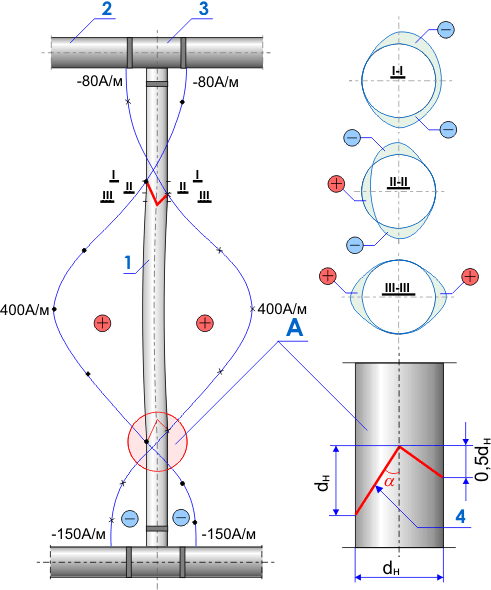
The Hp field value in the maximum flexure area along the entire pipe perimeter (compressed, extended and neutral) is practically the same and equal to 400A/m. The measurement results correspond to the design regularities obtained in the course of special methodic investigations. The Hp field distribution with sign alternation in zones of the pipe strain sign alternation (see unit A in Fig.1) should be specially considered. As it is seen in the figure, the Hp=0 line location has a regular nature. The many-years experience in magnetic fields investigation on pipelines and various metal components revealed presence of stable lines of sign alternation of the Hp magnetic field intensity normal component in areas of developing metal damages. This very diagnostic parameter (the Hp=0 line) was taken as a basis of practical techniques for inspection of metal components using the magnetic memory of metal. Papers [1, 2] showed that Hp=0 lines, recorded on the pipe surface, correspond to dislocations glide planes along the pipe section. The direct experimental confirmation of the Hp=0 line coincidence with the stress concentration line (SCL)3) and with the maximum dislocation density was obtained in paper [3].
3) In later investigations it was established that SCL in a general case correspond to the line of the maximum Нр field gradient (dHp/dx).
Fig.2 shows basic regularities characterizing the SSS of the pure iron during the mechanical exposure, which were obtained in paper [1] as a result of design investigations. It is seen in fig.2, b, that the glide plane angle relative to the normal tensile stresses has much lower values as compared to compressive stresses. For example, at tensile stresses of 12 kg/mm2 for the pure iron the glide plane angle is equal to ~45° , and at compressive stresses of the save value of 12 kgг/mm2 this angle is equal to ~70°. Based on the results of the Hp field measurements, presented in fig.1, simple calculations of glide plane angles indicate the following. The angle between the Hp=0 line and the pipe axis on the side of tensile stresses is equal to:

where c - is the glide line length (Hp=0).
The angle between the Hp=0 line and the pipe axis on the compressive stress side is equal to (90°-26,5°)=63,5°. Thus, by means of simple geometric calculation of the angle of the Hp=0 lines arrangement relative to the pipe axis, which were detected during the inspection by the MMM method, the fairness of regularities established in the paper [2] was confirmed. In presence of the dependence α(σ) for steel 3, being similar for the pure iron (see fig.2,b), based on the data of the inspection by the MMM method, it is possible to determine the value and the sign of residual stresses directly on the pipeline by the angle α.
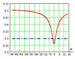
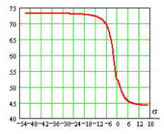
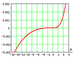
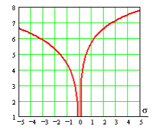
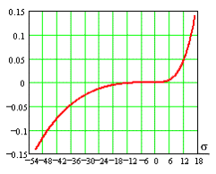
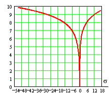
Fig.2. Basic dependencies characterizing the SSS of the pure iron during the mechanical exposure: a - Poisson's ratio; b - the glide plane angle; c - shear strain; d - density of dislocations N=10nd; e – shear strain; f - density of dislocations N=10nd, σ - mechanical tensile and compressive stresses, kG/mm2; σpc=0,95; σy=4,3; σt=17; εt=0,14.
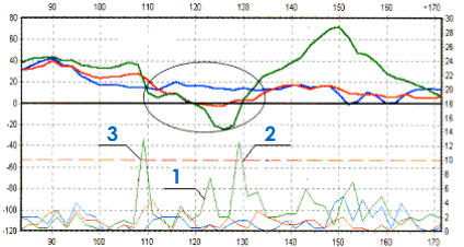
Fig.3 shows inspection results of a live steam pipeline section (branch B) obtained at power unit #1 at Konakovo TPS. It is seen in Fig.3,b (the bottom part of the diagram) that the field normal component gradient (dH/dx) when intersecting with a crack (Cr1) with the length of 60mm and the larger opening, has the value being 1,5 times less than at intersecting with a crack (Cr2) with the length of 7 mm and the less opening. It is also seen in Fig.3,b that the field gradient in the SC zone turned out to be approximately equal to the field gradient obtained on the crack (Cr2), being at the stage of initial development.
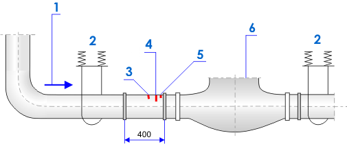
Assessment of absolute values of the residual stresses level in the SC zone (see fig.3), carried out according to the technique by Energodiagnostika Co. Ltd., shows that in this case this value (assessment was carried out by the normal component of the Hp field) sufficiently exceeds the ultimate strength of the steam pipeline's metal (steel 15Cr1Mo1V, σt=500-700 MPa). It is well agreed with the well-known provision that stress concentration level at the crack top may meet its critical value.
As it was pointed out above, according to the MMM method, the gradient of the magnetic leakage field Hp (dH/dx), recorded during scanning with the sensor of the TSC-type instrument along the surface of metal components, is a basic diagnostic SSS parameter. It was established that exactly this diagnostic parameter, by virtue of magnetometric effect, directly reflects the energy state of metal surface and depth layers in SCZs. The maximum value of the field gradient determined on the metal surface with accuracy of up to one millimeter corresponds to the source of crack initiation. In the area of the most intensive process of strain and, finally, failure the domain structure is subject to sufficient changes. Dimensions of domains, directions of which correspond to glide direction, meet critical sizes. Design researches in paper [4] showed that the critical size of an iron domain might have the volume covering up to ten grains. The domain with maximum dimensions finally "breaks" - a crack forms. At present Energodiagnostika Co. Ltd. possesses quantitative criteria characterizing the limiting state of the metal by strength conditions and the initial development of cracks.
Paper [5] presents various examples from practice illustrating capabilities of the MMM method at inspection of SSS not only of pipelines but also of other various units of metal components and structures.
For example, the available experience of the 100% inspection of K-300 turbine rotors at Konakovo TPS, of K-200 at Cherepovets TPS and Zainskaya TPS, of T-100 at Severodvinskaya TPS-2, of PT-60 and T-100 at Petrozavodskaya TPS and others (more than 100 various-type turbines were inspection in total) allows drawing the following conclusion: SCZs - the sources of damages development (as a rule, in the form of cracks) - make not more than 3-5% of the entire surface and volume of the rotors' metal. The rest 95% of the metal volume of turbine rotors after their long-term operation remain in the satisfactory state! Thus, the problem of turbine rotors' lifetime assessment is solved by means of timely detection of maximum stress concentration zones and their removal by ordinary grinding in the course of the repairs. Energodiagnostika Co. Ltd. uses the similar approach during the lifetime assessment with the 100% inspection by the MMM method on all types of metal components: turbines, boilers, steam and water pipelines, gas and oil pipelines, vessels and other inspection objects.
Based on the 20-years experience of the MMM method practical application a conclusion can be made about its unique capabilities for detecting local SCZs, determining the actual SSS, reliability and lifetime of metal components. Besides, it should be once more pointed out that the absolute value of stresses in the local SCZ, characterized by glide lines with maximum values of the magnetic field gradient (the width of these lines of dislocations cluster is ~0,1÷10 micrometers) before initiation of a microcrack development is by order greater than the metal conventional ultimate strengt σt. It is obvious that in these conditions the traditional methods of stresses NDT, intended for determining of average stress values σ on long segments, turn out to be unsuitable for their practical application.
Bibliography
1. Dubov A.A. Boiler pipes diagnostics using the magnetic memory of metal. Moscow: Energoatomizdat, 1995, 112p.
2. Dubov A.A. Metal properties investigation using the magnetic memory method // Physical metallurgy and heat treatment of metals. #9, 1997, pp.35-39.
3. Goritsky V.M., Dubov A.A., Demin E.A. Investigation of steel samples structural damageability using the metal magnetic memory method // Control. Diagnostics. #7, 2000.
4. Vlasov V.T., Dubov A.A. Physical basics of the metal magnetic memory method. Moscow: ZAO "TISSO", 2004. 424p.
5. Dubov A.A. Diagnostics of equipment and structures strength using the metal magnetic memory method // Control. Diagnostics. #6, 2001, pp.19-30.