Process pipelines inspection without insulation removal using scanning devices and the metal magnetic memory method
Dr. Anatoly Dubov
In the course of industrial studies it was found that the main sources of all types of pipeline damages development, including corrosion, are stress concentration zones (SCZs), which occur due to unfavorable combination of a number of factors: process, installation, structural and operational (workloads).
In SCZs and in the areas of developing damages occurrence of magnetic anomalies is observed, the amplitude and frequency of which are associated with pipelines deformation and the type of corrosion and fatigue damage (pipe wall thinning over a long section, corrosion pits on the external and internal surface of the pipe, etc.). Thus, the main task in analyzing the results of heat lines inspection by the non-contact magnetometric method is to detect anomalies in the magnetic field distribution and to establish the relation of these anomalies with SCZs and various types of developing damages.
During pipelines inspection through an insulation layer, the criteria developed in the metal magnetic memory (MMM) method are used.
In SCZs, the pipeline deformation takes place together with the insulation layer that has rigid attachment to the pipe. Even in case the insulation includes a "chain-link" fastening mesh, information about off-design pipe deformation is transmitted through the mesh deformation in the form of magnetic anomalies recorded on the insulation surface.
Inspection by the non-contact magnetometric method, for example, of heat lines through an insulation layer is performed by two experts. One expert holds the TSC-type (Tester of Stress Concentration) instrument and monitors the magnetic field variation on the screen, and another expert moves the scanning device (SD) along the heat line surface (see Figure 1). In exceptional cases, inspection can be performed by one expert, who, while holding the TSC instrument, simultaneously moves the SD along the heat line surface. In practice, such inspection is possible if the heat line diameter does not exceed 500 mm.
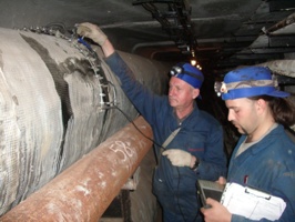
While travelling along the pipeline, the expert holding the instrument makes notes in a notebook about various types of obstacles and hindrances (supports and suspensions, pipeline bends, its intersection with other pipelines or with cable, presence of bypasses, drains, fittings, etc.). Recording of obstacles and hindrances can be made using a dictaphone recorder. Breakdown of the recorded information by individual files lengths is performed on-site, based on the actual pipeline routing and conditions of accessibility for inspection.
The scanning device used for inspection of pipelines through an insulation layer has 16 channels for measuring the normal component of the magnetic field. The SD flux-gate sensors are mounted on special arcs (Figure 2).
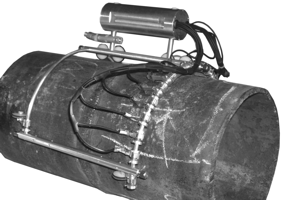
Depending on the pipeline diameter, the arc lengths and their bend radius are changed on the SD. During the inspection, only part of the pipe perimeter is covered, and scanning is performed along the surface available for inspection.
In case the instrument screen records a magnetic anomaly with parameters characteristic for the given pipe size, this should be recorded in the notebook and the location of this anomaly is marked on-site along the heat line length with reference to support numbers and other unit-forming elements of the scheme. The magnetic anomaly parameters depend on the insulation layer thickness, its quality and the pipeline diameter and should be specified in the technique.
Areas of detected magnetic anomalies, it is recommended to perform inspection along the pipeline perimeter in order to determine the maximum stress concentration zone in this pipeline section, which corresponds to the maximum value of the magnetic field gradient. Inspection along the pipe perimeter is performed with the same TSC instrument using a different (standard) scanning device (Figure 3).

Based on the results of non-contact (through the insulation layer) magnetometric pipeline inspection, the magnetograms analysis is performed, and test sections are identified (two or three sections per every 500 m of the pipeline length) for insulation opening and performing additional non-destructive testing by other methods (MMM method, ultrasonic testing, thickness measurement, visual and dimensional inspection, eddy current method).
When selecting sections for insulation opening it is recommended to compare the non-contact inspection results with the visual and dimensional inspection data and to take into account the pipeline operation time and its previous damages. Sections, where the detected magnetic anomalies coincide with structural stress concentrators (bends, sections with drains, branches, supports and suspensions) and with previously damaged areas, are opened for additional inspection as a matter of priority.
Upon the insulation opening on ~0,5÷1 m long sections, in order to localize SCZs, inspection by the MMM method is performed directly on the pipe metal. Then inspection by other NDT methods is performed in local SCZs.
Let us further consider some results of a heat network hot water supply pipelines non-contact magnetometric inspection in urban conditions.
Figure 4 presents an example of inspection results of a section of a ⌀500 mm heat line, located in the heat network straight-way collector.
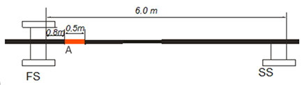
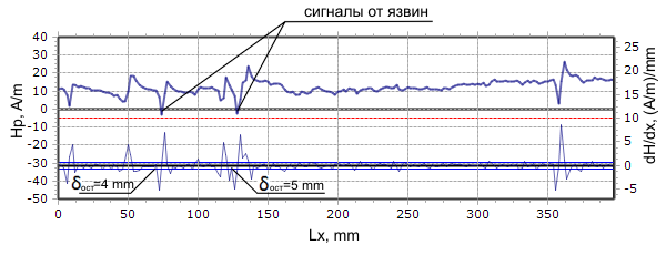
Figure 4. Inspection results of a section of a ⌀500 mm heat line, located in the heat network straight-way collector between the fixed (FS) and sliding (SS) supports:
a – scheme of the heat line section and the detected magnetic anomaly (A); b,c – results of the inspection along the heat line generating line, which coincides with the anomaly A, before and after the insulation opening.
The heat line is covered with ~ 60 mm thick asbestos insulation, which includes a "chain-link" metal mesh inside.
Figure 4, a shows this 6 m long section arrangement between the fixed (FS) and sliding (SS) supports, indicating the location of the magnetic anomaly A detected during the inspection using the above technique.
Figure 4, b shows the anomalous distribution of the magnetic field H (the upper part of the magnetogram) and its gradient dH/dx (the lower part of the magnetogram) recorded through the insulation layer on this heat line section.
Figure 4, c shows the distribution of the magnetic field H and its gradient dH/dx, recorded on the same heat line section after the insulation removal during the direct inspection by the MMM method on the pipe surface. In areas of local variations of the field and its gradient, the ultrasonic testing method detected corrosion pits on the internal surface of the pipe with wall thinning up to 4-5 mm instead of nominal 8 mm.
Figure 5 presents an example of the results of inspection through the insulation layer of a section of ⌀600x8 mm heat line, located in the heat network straight-way collector.
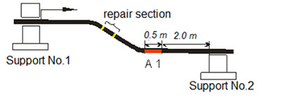
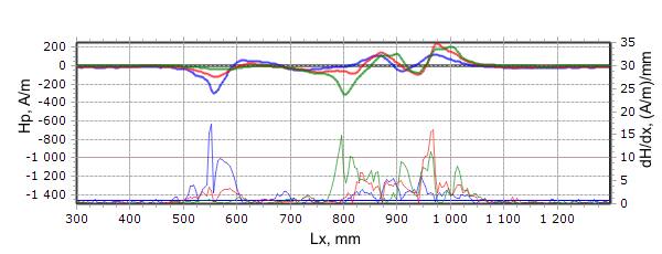
Figure 5. Inspection results of a section of a ⌀600x8.0 mm heat line, between the sliding supports No.1 and No.2:
a - section arrangement scheme; b - location of the magnetic field H and its gradient recorded in the area of the anomaly A1 along one of the measurement channels.
Figure 5, a shows this section arrangement between sliding supports No.1 and No.2 with the detected magnetic anomaly A1 near the heat line bend. The same scheme shows the location of the section to be repaired with new insulation, which previously had damage.
Figure 5, b shows the distribution of the magnetic field H and its gradient (dH/dx), recorded along three measurement channels through the insulation layer on the section with the anomaly A1. Similar variations in the field H and its gradient were recorded in zone A1 along all the 16 measurement channels of the scanning device, which covered approximately one third of the pipe perimeter. From Figure 5, b it is clear that the length of the section with A1 is approximately 600 mm, i.e. practically equal to the pipe diameter. The obtained inspection results indicate that this heat line section operates under conditions of increased compensation voltages at temperature expansions. Upon the insulation opening in the magnetic anomaly A1 zone, the direct pipe surface inspection by the ultrasonic testing method detected a number of local wall thinning zones (from 3.8 to 6.6 mm instead of nominal 8 mm) due to internal corrosion.
The above examples demonstrate the principle possibility to detect the most stressed areas susceptible to damages development by the non-contact magnetometric method on pipelines through the insulation layer.
In 2010 this method was used for inspection of 30 km of heat pipelines: 15 km of hot water supply pipelines and 15 km of cold water supply pipelines at the Moscow Heat Network Company OJSC. 122 sections susceptible to damages were identified. The total length of these sections is only 1% of the total length of the inspected heat lines. Based on the experimental survey, a guideline with classification of sections by the degree of hazard for damages development was developed, which can be used at many industrial plants having long pipelines covered with various process purpose isolation.