Problems of oil and gas pipelines' stress-strain state control and their solution using the metal magnetic memory
Dr. Anatoly Dubov, Dr. Alexander Dubov
On January 1, 2017, Rostekhnadzor order No. 316 of July 28, 2016 entered into force, which amends the Federal Industrial Safety Rules and Regulations "Rules for audit of industrial safety" approved by Rostekhnadzor Order No. 538 of November 14, 2013 (hereinafter referred to as "Rules").
In accordance with these Rules, the need for their stress-strain state (SSS) control (study) during the inspection of technical devices was established.
All leading diagnostic centers around the world are currently occupied with the problem of mechanical stress control in operated structures and pipelines in order to assess their condition. However, till date no effective stress control methods suitable for practical application have been proposed.
Analysis of the capabilities of the known methods for controlling stresses and strains in the base metal of equipment and structures components and welded joints allows us to name their essential drawbacks. The main drawbacks are:
- impossibility to apply most of the methods in the plastic strain area;
- locality of control, their unsuitability for inspection of long structures;
- metal structure variation is not taken into account;
- inspection is performed, as a rule, only on the components' surface due to existing problems of deep layers assessment of metal and welded joints metal;
- necessity to plot calibration curves on preliminarily fabricated specimens, which do not reflect the actual stress-strain state (SSS) of the equipment;
- preparation of the inspection surface and inspection objects (dressing, active magnetization, sensors adhering, etc.) is required;
- difficulty in determination of inspection sensors' position relative to the direction of action of maximum stresses and strains that determine the equipment and structures reliability.
It is known that the main sources of pipelines damages are stress concentration zones (SCZs), in which metal corrosion, fatigue and creep processes develop most intensively. SCZs are not only the areas known ahead, where the structure features create various conditions for distribution of stresses due to external work load, but these are randomly located areas where large strains (as a rule, shear strains) occurred due to initial inhomogeneity of the metal structure combined with off-design additional work loads. Structural and mechanical properties of the metal need to be primarily studied exactly in SCZs.
The known methods of non-destructive stress control (X-ray, ultrasonic testing (UT), Barkhausen noise, strain gauging, etc.) do not allow to solve this difficult task – determination of the actual SSS for extended oil and gas pipelines with detection of SCZs due to workloads.
In addition, conventional methods and means of non-destructive stress control, which are based on active interaction of the instrument signal with the structure metal, obtain indirect information about the inspected object's stress state, i.e. have insufficient information content of the physical fields used in the control. Any artificial physical field brought from the instrument into the test object in a stress-strain state (even after workloads relief), will surely interact with the material's own physical fields, for example, electromagnetic, formed at the crystal lattice level. The field introduced into the studied material, while interacting with the material's proper fields, changes its properties and SSS characteristics of the inspected object. At that the pattern, size and lifetime of variations are determined by the dynamic ratio of the interacting fields' energies. In practice, when conducting diagnostics, such variations are simply not taken into account. A gross mistake for all SSS control methods is not taking into account the actual energy state of the inspected object (this is evidenced, for example, by the magnetic memory of the metal)! This is especially true for SCZs, which are concentrated, as a rule, at a depth and in the volume, and come out on the product surface in the form of slip lines (crack formation sites!) with widths from fractions to a few microns. In addition, the inspection is carried out, as a rule, on equipment shut down for maintenance after workloads relief in conditions of residual SSS, when stresses and strains have opposite signs and different values compared to working ones. In these objective conditions, most inspection methods are ineffective for assessing the actual SSS of the inspected object, both by their physical essence and metrological conditions (locality in the maximum stress concentration zone – the zone of crack initiation – is fractions of a millimeter, and the size of instrument sensors generally significantly exceed this locality). And most importantly, it is not known where and how to mount the sensor, when, in a general case, the maximum stress (working or residual) zones formation sites are not known.
Thus, the above-mentioned disadvantages of the well-known SSS control methods are due to the physical essence of these methods and are expectable. The lack of metrological basis for certification and calibration of devices for materials' SSS characteristics measurement (till date there are no unified standards and specimens in Russia and other countries) result in ambiguity of initial requirements and fallacy of the methodical approach to the developed instruments and devices. Moreover, many experts, applying various stress control methods and means, are confident that they “measure stresses”, forgetting that only strain can be measured, and stresses are calculated using the calibration characteristic algorithm σ = f(ε) preprogrammed in the instrument processor.
Calibration of devices and techniques for stress measurement is carried out on specimens during their tensioning under static load on a tensile machine and, as a rule, in the elastic strain area. At the same time, it is known that real equipment operates under cyclic loading conditions, and the development of damages occurs in SCZs, in which the metal works in the plastic strain area. Moreover, the actual SSS of the equipment in many cases does not correspond to the design SSS, and in a general case, the actual distribution of strains and stresses by value, sign, direction, metal depth, is unknow.
The above-mentioned problems arising in practice during stress control cannot be solved within the framework of the formed concepts of internal stresses. Paper [1] for the first time provides a theoretically grounded and experimentally confirmed new concept of internal stresses as an integral characteristic of the metal's energy state in the actual product volume. This paper [1] also shows that calibration of stress control means and methods on specimens by conventional tensile tests is a fundamental mistake, since it is fundamentally impossible to transfer the obtained calibration characteristics on real equipment, both due to the scale factor and to the physical bases. In this case, the ideological basis for the “Stress Control” topic development should be the energy concept that reflects the objective processes of the material's proper energy redistribution as a reaction to external influence. In this regard, paper [2] presents new requirements for methods and means of stress-strain state diagnostics.
It should be noted here that the metal magnetic memory (MMM) method is the first method for the material's energy state diagnostics (energodiagnostics).
The MMM method does not require any preparatory operations (surface dressing, insulation removal or artificial magnetization). During SSS control of extended pipeline sections, the relation of the self-magnetic stray field (SMSF) with actual strain is used. Russian and international standards on the MMM method are available [3, 4, 5].
Experimental studies and practical results of the metal magnetic memory method application served as the basis for the development of an ideologically new energy approach to equipment and structures' stress-strain state assessment.
The energy approach is based on the idea that each component of a certain shape and material has certain energy intensity, characterizing its specific resistance to external loads and failure. Experimental studies found that the limiting state that occurs at a component (or some structural unit) failure, has the same energy characteristic, i.e. the energy of the component failure, irrespective of the various combination of factors and physical effects that led it to this state, is the same and is an energy constant. And the time to reach the limiting state, even for the same type of components, depending on the various combinations of factors, can be different. Based on the energy relationship between the magnetic and mechanical parameters obtained during static and cyclic load testing of the specimens using the MMM method, it becomes possible to transfer the SMSF calibration values from the specimens to the real equipment [6.7].
Currently, non-contact magnetometric diagnostics (NCMD) is more commonly used in practice for assessing the condition of oil and gas pipelines located under the soil layer [8]. NCMD is based on measuring the distortions of the magnetic field of the earth along the oil and gas pipeline route, caused by variation of the pipe metal magnetization in SCZs and in zones of developing damages.
During the pipelines NCMD, the magnetic parameters developed in the MMM method are used. In particular, in NCMD, like in the MMM method, a clear relationship between the variation frequency of all three components of the measured SMSF and the inspected pipe's dimension-type (diameter, wall thickness and pipe length between joints) was found. These qualitative diagnostic parameters characterize SCZs – sources of various damage types development - in the macro-volume of the pipe metal.
Currently pipelines covered with foamed polyurethane (PUF) insulation are more and more applied in installation of oil pipelines in northern Russia to reduce corrosive wear. However, on pipelines with PUF insulation, due to less heat loss from the pipe metal compared to conventional insulation, the pipe displacement during self-compensation is greater and, accordingly, the stress level in areas of their concentration is higher. At significant fluctuations of the external air temperature, due to the lack of self-compensation on individual segments of buried oil pipelines, their increased deformation occurs with exposure to the soil surface. “Forcing out” of oil and gas pipeline buried sections to the soil surface in marshy areas in winter also occurs on pipelines with standard insulation. On these segments high stress concentration on installation joints is formed with damages development in them.
Let us consider the NCMD efficiency for the actual SSS assessment on oil and gas pipeline sections “forced out” to the soil surface, using the following example. In November 2016 – January 2017, Energodiagnostika Co. Ltd. experts subsidiaries carried out the inspection at one of PJSC NOVATEK of 45 sections of ⌀ 377 × 10 mm PUF-insulated oil pipelines at the points of their coming out to the surface due to the increased uncompensated strain.
Figure 1, a shows the general view of one of such sections.
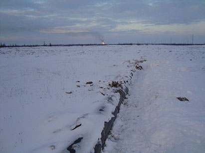
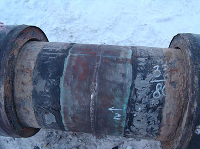
Figure 1. Oil pipeline section with increased uncompensated strain: a - general view of the section; b - field weld in the area of its opening
During the NCMD magnetograms were recorded using a magnetometric instrument - tester of stress concentration TSC-6M-8, complete with a specialized Type 11-6K scanning device (SD). When the operator moved along the pipeline route, magnetograms were recorded with breakdown by files. The start and end points of the file, as well as all intermediate points were marked in place with their subsequent recording in the GPS coordinate system. Figure 2 shows the instrument complex for NCMD, mass-produced by Energodiagnostika Co. Ltd.
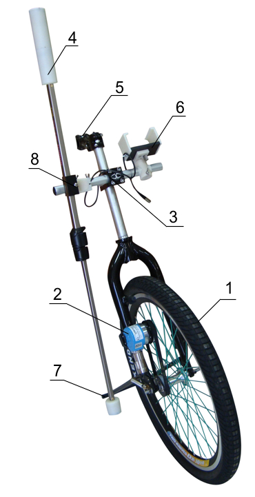
Figure 3, a shows the scheme of ⌀ 377 × 10 mm oil pipeline routing on section ПК 59+60, and Figure 3, b – the magnetogram recorded during the NCMD of this section.
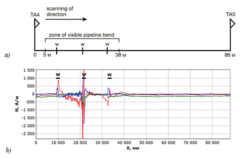
Comparison of Figure 3, a and Figure 3, b shows that abrupt local variations of the oil pipeline's self-magnetic stray field (SMSF) were recorded during the NCMD in the zone of visible oil pipeline bend and its coming out to the soil surface (Figure 1). At that, the maximum SMSF variations coincide with locations of the girth welded joints.
Additional inspection by the MMM method (contact method) and UT (ultrasonic testing) was performed on the second welded joint with the maximum H field variation after the insulation (protective covers) removal. Figure 1, b shows the field weld in the area of its opening, and Figure 4 shows the results of this weld inspection by the MMM method with marking of the identified stress concentration zones as SCZ1 and SCZ2.
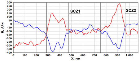
Ultrasonic testing of this welded joint in SCZ1 and SCZ2 revealed unacceptable defects in the form of extended discontinuity flaws at a depth of 2 to 7 mm. Defects were located in the welding heat-affected zone on the maximum plastic strain side of the adjacent pipeline section. This field joint was recommended for replacement.
Another 44 sections of a total length of about 5 km with visible oil pipeline deformation were inspection in similar way using the NCMD and MMM methods. 20 magnetic anomalies characterizing SCZs with maximum strain near welded joints were detected. Almost all magnetic anomalies with significant variation of the pipeline's self-magnetic field H coincided with locations of transverse (girth) welded joints.
The presented example of actual SSS control of oil pipelines extended sections using the NCMD, MMM method and UT convincingly demonstrates the efficiency of such comprehensive inspection. It is obvious that the oil pipelines’ actual SSS assessment with detection of the most stressed sections, located in swampy and heavy-going places, using calculation methods and well-known methods of SSS NDT (X-ray, ultrasonic testing (UT), Barkhausen noise, strain gauging, etc.), referred to laboratory research methods, is impossible in these conditions.
References
1. V.T. Vlasov, A.A. Dubov. Physical theory of the "strain-failure" process. Part I. Physical criteria of metal's limiting states. Moscow: Publishing House "Spektr", 2013. 488 p.
2. A.A. Dubov. New requirements to methods and means of materials' stress-strain state diagnostics // Mir izmereniy, 2012, No.6. pp.38-42.
3. ISO 24497-1:2007(E) Non-destructive testing - Metal magnetic memory - Part 1: Vocabulary.
4. ISO 24497-2:2007(E) Non-destructive testing - Metal magnetic memory - Part 2: General requirements.
5. ISO 24497-3:2007(E) Non-destructive testing - Metal magnetic memory - Part 3: Inspection of welded joints.
6. N.A. Makhutov, A.A. Dubov, A.S. Denisov. Study of statistic and cyclic strains using the metal magnetic memory method // Zavodskaya laboratoriya, 2008, No.3. pp.42-47.
7. A.A. Dubov. Investigation of steel specimens fatigue failure process using the metal magnetic memory method // Territory of NDT, 2016, No.3. pp.40-43.
8. A.A. Dubov, Al.A. Dubov. Experience in application of pipelines non-contact magnetometric diagnostics and prospects for its development // Control. Diagnostics, 2015, No.10. pp.21-24.