Purpose and practical capabilities of the metal magnetic memory method
Dr., Professor A.A. Dubov
Fundamental differences of the metal magnetic memory (MMM) method from other magnetic non-destructive testing (NDT) methods were repeatedly reported in articles [1, 2, 3] and in theoretical studies [4, 5, 6].
The main purpose of the MMM method is detection on equipment and structures of stress concentration zones (SCZs) - the main sources of damages development – in the express control mode using specialized instruments and scanning devices.
SCZs are not only pre-known areas where the design features create different conditions for distribution of stresses caused by an external load, but these are also randomly located areas, in which due to the initial metal heterogeneity combined with off-design additional workloads large strains (as a rule, shear strains) occur.
Geometric feature of magnetic anomalies that characterizes SCZs is the distance between self-magnetic field extreme values multiple of the standard size of a product (thickness, width, diameter). This distance corresponds to the minimum distance between the adjacent glide pads or the shell critical size occurring, for example, at the pipe stability loss.
Inspection by the MMM method is carried out without metal dressing and artificial magnetization. The method uses residual magnetization formed naturally during the products manufacture and in the course of their operation.
Of course, one can doubt the detection of SCZs and various metal defects detection by magnetic anomalies on products with unknown prehistory [7]. However, it is known that the criterion of the truth is practice! Numerous studies carried out by the authors of the method at manufacturing plants showed that all products of the same type, made of the same steel grade and under the same technology, have almost the same distribution of the residual magnetization, and magnetic anomalies are only identified during the inspection in the areas of residual stress concentration and different structural irregularities on individual products. And this is not surprising, since during formation, for example, of thermoremanent magnetization of products in the course of their manufacture, internal stresses, and not the weak external geomagnetic field, play the decisive role.
In the course of products operation the initial residual magnetization (RM) is redistributed under the effect of workloads, and magnetic anomalies, caused by geometric displacements and product standard size, occur in SCZs.
If local SCZs do not occur in the same-type products under the effect of workloads, it the RM distribution pattern in them is practically the same. To make sure of this, it was necessary to inspect thousands of same-type units and products! Based on the established regularities and substantial practical experience in inspecting various units of equipment and structures, the authors proposed a methodology of standardless calibration of inspection equipment and methods, as well as their respective metrology [3].
Diagnostic parameters in the MMM method
1. In accordance with GOST R ISO 24497-1-2009 [8] the MMM method is a non-destructive testing method based on recording and analysis of the distribution of the self-magnetic stray fields (SMSF) that occur on products and equipment in stress concentration zones (SCZs).
SMSF that reflects residual magnetization formed naturally during the product manufacture should be distinguished from magnetic leakage fields (MLF) occurring on metal defects and cracks at artificial magnetization of a product (for example, in the course of the magnetic particle inspection).
2. For quantitative assessment of the level of stress concentration (sources of damages), the gradient of the normal (Hy) and/or tangential (Hx) SMSF components is determined:
Kin = |ΔНy| / Δx, at Δx->0 Kin = dН / dx, (1)
where Δx - is the distance between the adjacent points of inspection.
In some cases during the inspection of equipment stress-strain state (SSS) the resulting SMSF gradient is used:
3. Among the basic calculation diagnostic parameters the MMM method uses the parameter m that characterizes the ultimate strain capability of the material:
m = Кinmax / Кinave, (2)
where Кinmax and Кinave are the maximum and the average values of the field gradient, respectively, which are determined during the inspection by the MMM method of the same-type equipment units.
Industrial and laboratory tests on the specimens established the relation between the limiting values of magnetic and mechanical parameters:
mlim = Кinmax / Кinave ≈ Кinlim / Кint ≈ σlim / σt, (3)
Experimental studies also established that if the actual parameter mact ≥ mlim, then in this case the limiting (critical) state occurs in the controlled equipment unit metal, at which a macrocrack forms. Physical substantiation of the parameter mlim can be found in papers [3, 4, 5].
It should be noted here that the opening of macrocracks at achieving the metal's limiting state amounts to fractions of a millimeter, which is a dead zone for the majority of NDT methods. Therefore it is incorrect to compare the results of inspection by the MMM method, for example, with the results of UT, X-ray or VT. And any comments about the MMM method on over reject or under reject are not acceptable. The methods used for confirmation of the results of inspection in SCZs with the limiting state of the metal are: metallography, hardness measurement or control performed, for example, by ultrasound at the search level.
If the values of the actual magnetic parameter mact are significantly higher than mlim, i.e. mact ≥ mlim, the size of cracks or various defects in SCZs become commensurable to the reject values in accordance with the existing norms for UT, X-ray, etc. And in this case, in the course of additional inspection by other NDT methods, such defects can be detected.
However, the problem is to identify these areas directly on the equipment metal and welded joints due to the small size of the SCZs and the lack of information about their location. As a rule, SCZs occurrence locations do not coincide with the calculated data. Combination of the results of inspection by the MMM method with other NDT methods dramatically increases the efficiency of inspection. At present the MMM method is widely used exactly in such complex inspection of the base metal and welded joints. SCZs are detected on the Inspection Object (IO) by the MMM method in the express-control mode without any surface preparation, then they are classified by the SMSF gradient and by the design parameter m, and after that the specified SCZs are additionally inspected by ultrasound or other NDT methods.
Let us further consider individual examples from the practice of the MMM method application.
Figure 1 shows the scheme of pipeline and vessel welds inspection using the Type 1-8M scanning device and the TSC type (tester of stress concentration) instrument.
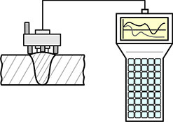
Figure 1. Scheme of pipeline and vessel welds inspection using the Type 1-8M scanning device and the TSC type instrument.
Figure 2 shows the MMM inspection results of a polymerization reactor girth weld at Anwil enterprise (Wloclawek, Poland).
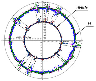
The external part of the circular magnetogram corresponds to SMSF (Н), and the internal part corresponds to SMSF gradient (dH/dx) distribution along the weld perimeter. Dotted lines indicate the SCZs detected during the inspection. In all SCZs additional ultrasonic testing (UT) was recommended.
Upon comparing the results of inspection by the MMM and the UT methods, the permissible defects rejection level by the SMSF gradient (dH/dx). was established. Subsequently, this rejection level was used during the MMM inspection of similar welds.
Figure 3 shows the fragment of a gas pipeline inspection through the insulation layer using a scanning device (SD) with highly sensitive SMSF measuring sensors.
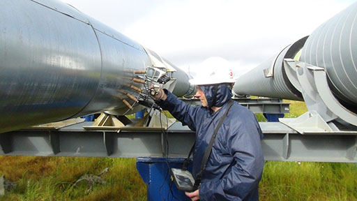
Pipelines in foamed polyurethane (PUF) insulation have become widely used to reduce corrosion wear of metal. However, on pipelines with PUF insulation, due to less heat loss from the pipe metal compared to conventional insulation, the pipe movement during self-compensation is greater and, accordingly, the stress level in zones of their concentration is higher. In addition, when pipelines are laid on piers installed in areas with unstable soils and in wetlands, there is a problem of ensuring the design movements, which contributes to damages occurrence. At that, the main areas of SCZs formation are heat-affected zones (HAZ) during field welding. Poor-quality field welding, combined with high level of stresses with lack of thermal expansion self-compensation, causes formation of cracks in welding HAZ.
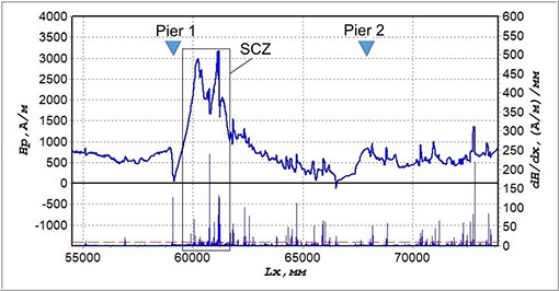
Figure 4 shows MPM-inspection results of a section of ⌀ 820 × 10 mm oil pipeline laid on piers near the U-shaped expansion bend. The upper part of the magnetogram shows SMSF (Н) distribution, and the lower part – the dH/dx gradient distribution, measured along the insulation surface. It can be seen from Figure 4 that near the pier #1, compared to the pier #2, the SMSF distribution anomaly is recorded, which characterizes formation of SCZs.
After the insulating sleeve removal at the field welded joint located in the SCZ, the MMM inspection was performed along this joint perimeter directly on the pipe metal. Figure 5, a shows the magnetogram recorded during the joint inspection by the MMM method. Several local SCZs, characterized by high SMSF gradient (dH/dx) values, were detected in the lower part of this joint. Then, ultrasonic testing was performed in these zones. Based on the UT results, unacceptable defects in the form of extended discontinuity flaws were detected on this joint in HAZ at a depth of 8 to 10 mm (near the weld root). For comparison, Figure 5, b shows the magnetogram recorded on the field welded joint, located near the SCZ-free pier #2. It can be seen that the distribution of SMSF gradient (dH/dx) on this joint is relatively uniform. No unacceptable defects were detected on this joint during the UT.
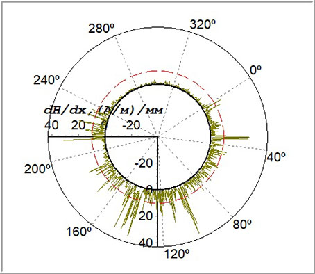
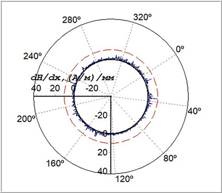
Figure 5. Results of MMM-inspection of a field girth joint located in a SCZ (a), and of a field girth joint in a satisfactory condition based on the MMM-inspection results (b).
Another 9 field welded joints located in SCZs near the piers were opened on the ⌀ 820 × 10 mm oil pipeline, and unacceptable defects in the form of discontinuity flaws were detected in HAZ on all joints during the additional NDT directly on the metal using the MMM and UT methods.
One of the challenges in ensuring the reliability of rotating mechanisms is preventing sudden fatigue damages of shafts, rotors, disks, blades and other components of turbine, pump and compressor units. As practice shows, the use of magnetomechanical memory due to hysteresis is effective exactly for solving this problem. Residual magnetization formed under the effect of actual workloads and the measured SMSF of inspected units directly reflect formation of SCZs – sources of damages at the very early stage of their development.
Figure 6 shows the magnetograms recorded in 2019 during the inspection of blades #15 and #17 of rotor stage #9 of K-15-41 steam turbine in the ammonia production shop of JSC URALCHEM (Kirovo-Chepetsk).
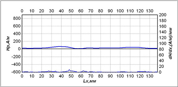
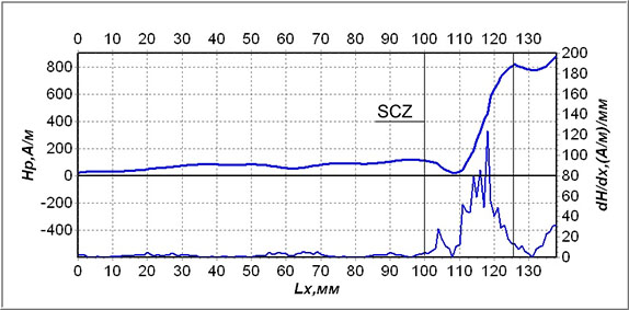
Figure 6. Results of the inspection by the MMM method of blades #15 (a) and #17 (b) of K-15-41 turbine stage #9.
As of the date of inspection the stage #9 blades' operating time was ~ 190.000 hours. However, it can be seen from Figure 6 that based on the MMM-inspection results, these blades are in different condition. An abrupt local variation of the magnetic field Н and its gradient (dH/dx), characterizing a SCZ, was identified on the blade #17 (Figure 6, b). In the course of additional mechanical properties inspection by measuring hardness in the blade #17 SCZ, Brinnel hardness (HB) decrease to a value of 188-192 kgs/mm2 was noted. The hardness value (HB) on the blade #15 was in the range of 216-225 kgs/mm2, which is admissible for steel 20Cr13. Hardening was recorded on individual blades of this stage in SCZs: the hardness value (HB) reached 260 kgs/mm2.
During prolonged cyclic loading of blades, the surface layer is first hardened and then softened ("loosened") due to formation of microcracks. Therefore, in order to ensure reliability of blades with identified SCZs if there is no possibility of their replacement, it is recommended to perform surface grinding with removal of the damaged metal layer.
In conclusion, the main purpose of the MMM method and its application scope should be once more noted:
- express control of mechanical engineering products' quality for metal defects and local SCZs detection;
- early diagnostics of corrosion-fatigue damages and residual lifetime assessment of equipment and structures;
- defects detection (lamination, casting defects, etc.) in the deep layers of metal through the use of SMSF geometric parameters conditioned by dislocations glide pads in SCZs;
- 100% inspection of IO to detect local SCZs - sources of damages development;
- improving the efficiency of IO NDT due to application of the MMM method in combination with other NDT methods;
- reduction of material costs for performance of inspection due to refusing the use of artificial magnetization of IO and surface dressing (and in some cases - of insulation removal from IO).
The use of the MMM method provides the opportunity to study the metal's structural and mechanical properties at the physical level during specimens laboratory testing.
The use of the MMM method applies to any products made of ferromagnetic and paramagnetic material. At present in power engineer, petrochemical, oil, gas and other branches of Russian industry the MMM method is included in a number of guidance documents and industry standards (more than 60 documents).
References
1. A.A. Dubov. Fundamental distinctive features of the metal magnetic memory method and inspection instruments compared to the known magnetic non-destructive testing methods // Control. Diagnostics, 2003, No.12. pp. 27-29.
2. A.A. Dubov. Fundamental difference of the metal magnetic memory method from other known magnetic NDT methods. Results and prospects of the method development // Territory of NDT, 2016, No.2. pp. 64-68.
3. A.A. Dubov. Metrological aspects in the metal magnetic memory method // Mir Izmereniy, 2018, No.3. pp.42-45. No.4. pp.16-184.
4. V.T. Vlasov, A.A. Dubov. Physical bases of the metal magnetic memory method. Moscow, ZAO "Tisso", 2004, 424 p.
5. V.T. Vlasov, A.A. Dubov. Physical theory of the "strain-failure" process. Part I. Physical criteria of metal's limiting states. Moscow: Publishing House "Spektr", 2013. 488 p.
6. V.T. Vlasov, A.A. Dubov. Physical theory of the "strain-failure" process. Part II. Process thermodynamics. Moscow: Publishing House "Spektr", 2016. 223 p.
7. E.S. Gorkunov, A.G. Efimov, A.E. Shubochkin, B.V. Artemyev. On the question of magnetic NDT application to determine the stress-strain state of metal structures // World of NDT, 2016, No.3. pp. 52-55.
8. ISO 24497-1:2007(E) Non-destructive testing - Metal magnetic memory - Part 1: Vocabulary.
9. ISO 24497-2:2007(E) Non-destructive testing - Metal magnetic memory - Part 2: General requirements.
10. ISO 24497-3:2007(E) Non-destructive testing - Metal magnetic memory - Part 3: Inspection of welded joints.
11. A.A. Dubov. Monitoring of risks based on early diagnostics of equipment and structures metal state in stress concentration zones – sources of damages development // Himicheskaya tekhnika, 2016, No.4. pp. 26-28.
12. A.A. Dubov. New requirements to methods and means of materials' stress-strain state diagnostics // Mir izmereniy, 2012, No.6. pp. 38-42.
13. GOST R 52330-2005. Non-destructive testing. Evaluation of deformations in industrial and vehicle structures. General requirements.
14. GOST R 53006-2008. Estimation of potential dangerous objects lifetime on the basis of express methods. General requirements.