Detection of local stress concentration zones in engineering products - the lacking link in the non-destructive testing system
Dr., Professor A.A. Dubov
It is known that the main sources of damaging during engineering products operation are local stress concentration zones (SCZs) that form under the effect of working loads, first of all, on metallurgical and process defects.
Metallurgical and process manufacturing defects are known to cause high level of residual stresses (RS) in local zones of the product. RS control at some productions is performed on a selective basis. In this case the average (volumetric) level of RS is inspected, and local RS zones due to internal defects of the metal, as a rule, are not inspected and omitted. Besides, the location of these local zones and the method of their detection are unknown.
As a rule, RS control during the incoming inspection is not performed. For these reasons, during the very first years of products operation under the working load their "rejection" takes place. Process and metallurgical defects, causing the high level of RS in local zones of products at unfavorable combinations with stresses due to working loads, cause accelerated development of damages.
It is known that conventional NDT methods - X-ray, ultrasonic testing, the eddy-current method, magnetic powder and dye penetrant inspection - are aimed at searching and detection of pronounced defects located primarily on the products’ surface. Internal casting defects, various types of structural inhomogeneity as well as manufacturing process defects (welding, rolling, bending, heat treatment defects, etc.) remain undetected in products due to the lack of 100% quality inspection at most of the plants as well as due to imperfection of NDT methods applied. Moreover, these rejection standards of NDT methods used at products manufacturing plants are aimed at detection of defects with sizes that many times exceed those of metallurgical defects. For example, according to the norms of austenite pipes ultrasonic testing, the sizes of admissible defects do not exceed 25 mm in length and 0,3 mm in opening and depth. As practice shows, metallurgical defects of smaller sizes, when exposed to working loads, are the main sources of operational damages. In conditions of products operation practically all NDT methods are also aimed at detection of various-type discontinuity flaws with sizes significantly exceeding the size of defects that cause the development of damages.
Thus, it must be stated that the lack of RS inspection in order to detect stress concentrations on structural defects of products, both at manufacturing plants and during operation, is the lacking link in system of products NDT, which considerably reduces their safety and reliability.
Figure 1 shows the scheme of engineering products NDT arrangement that formed at present both at manufacturing plants and during operation. It can be seen in figure 1 that products inspection consists in the usual flaw detection without any assessment of stress concentration level on apparent (discontinuity flaws) and implicit (structural) defects. The lacking link in the NDT system is marked with a dotted line in figure 1.
It should be noted that nowadays, when in most industries equipment and structures became obsolete and worn out, and the material resources are not sufficient for their mass replacement, the value of non-destructive testing and technical diagnostics gains more relevance. In these circumstances the role of quick NDT methods increases in order to ensure 100% equipment inspection and detect local SCZs, in which damages development can be expected in the course of further operation of various technical devices.
In 2008 the National Standard GOST R 53006-2008 "Lifetime assessment of potentially dangerous objects based on quick methods. General requirements" was put into effect.
Passive NDT methods that use the internal energy of structures' metal are referred to quick methods:
- acoustic emission (AE) method;
- metal magnetic memory (MMM) method;
- thermal control.
At present these method have become the most widespread in practice for early diagnostics of equipment and structures damaging. The fundamental difference of such an approach to the lifetime assessment is performance of the 100% IO examination with detection of all potentially hazardous stress concentration zones (SCZs) - the sources of damages occurrence during the equipment operation.
The new National Standard GOST R 53006-2008 also contains the following basic provisions:
- it is suggested to use actual energy characteristics, which can be detected by the MMM, AE and thermal methods, as basic criteria of the metal's limiting state;
- block diagram for residual life determination with focus on modern quick methods is proposed;
- it is suggested to perform verification strength calculations with residual life assessment for SCZs remaining in operation considering the metal's actual structural and mechanical properties determined during the inspection;
- recommendations of the National Standard GOST R 52330-2005 "Non-destructive testing. Stress-strain state control of industrial objects and transport. General requirements" were taken into account.
At implementation of the GOST R 53006-2008 standard it is possible to perform the lifetime expert estimation based on the complex examination of the equipment and to specify safe operation time in most cases without carrying out complex calibration strength calculations. It is possible to develop more specific technique for specific equipment considering the specific features and requirements of this industry.
The metal magnetic memory (MMM) method developed by Energodiagnostika Co. Ltd. (Moscow) becomes more practically implemented for solution of the problem of determination of local SCZs in new and operated products. Russian and International standards on the MMM method are published.
In accordance with GOST R ISO 24497-1-2009 "Non-destructive testing. Metal magnetic memory method. Terms and definitions" the MMM method is a non-destructive testing method based on recording and analysis of distribution of self-magnetic leakage fields (SMLF) occurring on stress concentration zones (SCZs)1 and of structural inhomogeneity of products. IN this case SMLF reflect the irreversible variation of magnetization in the direction of the effect of maximal stresses due to working (external) loads, as well as structural and process history of products and welded joints after their fabrication and cooling in the magnetic field of the earth.
1)One should distinguish the traditional concept "stress concentrator" from the material science concept "stress concentration" occurring on structural defects and in zones of stable dislocation slipbands conditioned by the effect of working loads.
The MMM method differs fundamentally from all known magnetic NDT methods by the fact that its application does not require artificial magnetization of the product, but it uses the natural magnetization and aftereffect that appears in the form of the magnetic memory of metal related to actual strains and structural changes.
The MMM method requires no preparatory works during the inspection and differs from other NDT methods by the fact that it indicates the level of stress concentration, i.e. it indicates the degree of the detected defects' hazard.
Let us further consider the MMM method's capabilities at diagnostics of new and operated products in order to detect local SCZs - the sources of damages development.
Fig.2 shows the inspection results of a new ⌀22mm (St.05Cr16Ni4Сu2BТ13) rod used for fabrication of the shaft of electrical centrifugal pump (ECP) manufactured at LLC "PC Borets" production works (Lebedyan').
Figure 2, а shows the distribution magnetogram of the normal component of the self-magnetic leakage field Н and its gradient dН/dх recorded in the stress concentration zone (SCZ) during scanning with the instrument sensor along one of the generating lines of the rod №2204. Figure 2, b shows the metal's structural state of the rod №2204 in the section that coincides with the SCZ. Figures indicate the micro hardness values along the line of a metallurgical defect and outside it.
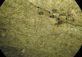
Figure 2. Inspection results of a new ⌀22 mm (St.05Cr16Ni4Cu2BТ13) rod used for fabrication of the shaft of electrical centrifugal pump (ECP) manufactured at LLC "PC Borets" production works (Lebedyan'): a - distribution magnetogram of the normal component of the self-magnetic leakage field Н and its gradient dН/dх, recorded in the stress concentration zone (SCZ) during scanning with the instrument sensor along one of the generating lines of the rod №2204; b - metal's structural state of the rod № 2204 in the section that coincides with the SCZ. Figures indicate the micro hardness values along the line of a metallurgical defect and outside it.
Figure 3 presents the results of inspection by the MMM method of a new hydraulic turbine blade. Figure 3, a shows the distribution of the magnetic field Н and its gradient dН/dх recorded during the inspection along the external surface of the blade. SCZ characterized by local variations of the field gradient is indicated in the bottom part of the magnetogram. Figure 3, b shows casting defects detected in the metal depth after cutting of the blade opposite the SCZ recorded by the MMM method on the external surface.
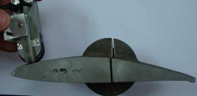
Figure 3. Results of inspection by the MMM method of a new hydraulic turbine blade: a - distribution of the magnetic field Н and its gradient dН/dх recorded during the inspection along the external surface of the blade; b - casting defects detected in the metal depth after cutting of the blade.
Figure 4 presents the results of inspection by the MMM method of a ⌀42x7mm pipe of steel 10Cr13G12BS2Ni2Cu2 cut out of the new power boiler platen superheater. Figure 4, a shows the distribution magnetogram of the self-magnetic leakage field dН and its gradient dН/dх recorded in the SCZ on one of the pipe generating lines. Despite the fact that this pipe was fabricated of stainless steel that should be practically non-magnetic in the initial (as-fabricated) state, however, a ferrite phase, recorded during the inspection by the MMM method as a magnetic anomaly, formed in the local zone due to violations of its manufacturing technology. Figure 4, b shows the cracks detected on the internal surface of the pipe cut out from the zone of the magnetic anomaly that corresponds to the SCZ.
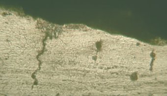
Figure 4. Results of inspection by the MMM method of a ⌀42х7mm pipe of steel 10Cr13G12BS2Ni2Cu2 cut out of the new power boiler platen superheater: a - distribution magnetogram of the self-magnetic leakage field Н and its gradient dН/dх recorded in the stress concentration zone (SCZ) on one of the pipe generating lines; b - cracks detected on the internal surface of the pipe sample cut out from the SCZ detected by the MMM method.
The presented in figures 2, 3 and 4 example from the practice of the MMM method application on new products of various productions clearly demonstrate general drawbacks in organization of NDT at manufacturing plants. All the above-mentioned products were tested by the NDT system currently existing at plants. However, as it was noted above, at present most of the manufacturing plants lack the inspection for detection of metal defects beyond the standardized sensitivity limits of the applied inspection methods and means. Application of the MMM method, which reveals metallurgical and technological production defects in the form of magnetic anomalies corresponding to local stress concentration zones, would allow to ensure the 100% products inspection even in mass production.
During operation of engineering products the major sources of damages development are also local SCZs, the formation sites of which are practically impossible to predict by calculation methods. Application of the MMM method offers a unique opportunity to detect the local zones with maximum stress concentration at an early stage by means of performance of the 100% inspection of various equipment units.
For classification of magnetic anomalies, characterizing SCZs by the degree of their hazard in accordance with the technique described in [1], a comparison of all magnetic anomalies detected on a specific unit by the field gradient dН/dх value is performed.
For the same-type equipment units, based on the laboratory and industrial investigations, the limiting value of the field gradient is determined, at which a microcrack is formed and the damage development starts.
In accordance with the definitions presented in paper [2], the physical sense of the magnetic parameter dН/dх is that it reflects concentration (or density) of the magnetic energy in the product's volume conditioned by the strain energy density.
Figure 5 presents the inspection results of a 120 MW steam turbine stage disk rim. Figure 5, a shows the magnetogram recorded on the external surface of the disk rim. The upper part of the magnetogram shows the distribution of the tangential 2 and the normal 3 components of the self-magnetic field Н, and the bottom part shows the distribution of the field gradient from the above-mentioned components. The maximum value of the field gradient 55 (A/m)/mm (or 55x103A/m2 )turned out to be approximately equal to the limiting state for this turbine disk. Therefore in this case additional inspection by ultrasonic testing was performed. Mounting of the UT transducer on the disk was adjusted to the maximum field gradient value location site. During performance of the UT a discontinuity flaw was recorded in the SCZ on the internal slot surface. After cutting out of the disk segment a 2 mm deep and20 mm long crack was detected on the internal slot surface (see figure 5, b and figure 5, c).
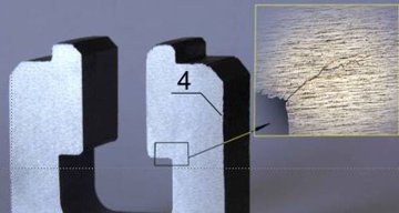

Figure 5. Inspection results of a 120 MW steam turbine stage disk rim: а - magnetogram fragment recorded on the external surface of the disk rim with upward shift approximately by 45 degree from the crack location on the internal surface of the disk; b - location of the detected ~2mm deep crack; c - location of the ~20 mm long (lk) crack along the internal surface of the disk rim; 1 - maximum value of the gradient dН/dх; 2 - distribution of the tangential component of the field Н; 3 - distribution of the normal component of the field H; 4 - zone of inspection by the MMM method on the external side of the disk before the fragment cutout.
It should be noted here that at present, in accordance with the effective guideline [3], turbine disks with T-shaped blades attachment are inspected by ultrasonic testing for cracks detection in slots with the use of special specimens, but the inspection itself is a complex practical task. During the performance of the disk rim UT combined with the MMM method the technique of UT signals comparison in the SCZ, pre-detected by the MMM method, and outside this zone can be used instead of a standard specimen. In these conditions standard specimens are not required, and the ultrasonic testing can be performed by an expert with medium qualification.
The considered example of the MMM method application for detection of the local SCZ at an early stage of the damage development clearly demonstrates the significance and efficiency of its application in combination with other NDT methods. The experience of the MMM method application on different equipment under long-term operation in various industries shows that only 5 to 10% of the total metal volume reaches the limiting state (physical ultimate strength) and achieve the stage of damage development. Unfortunately, it is practically impossible to determine these local SCZs - the sources of damages development - by calculation methods. Such problem can be solved using the methods of early diagnostics (the MMM and AE methods).
During the analysis of products fracture mechanism determination of local zone dimensions (volume, area, length), at which the limiting state of the metal and the product itself occurs, is the most valuable. Exactly this challenge, that has so far been the subject of study on specimens in fracture mechanics, is solved using the MMM method directly on the equipment during the diagnostics of various units' condition.
References
1. A.A. Dubov, Al. A. Dubov, S.M. Kolokolnikov. Metal magnetic memory method and inspection instruments: Training handbook. Moscow: ZAO "Tisso", 2008. 364 p.
2. V.T. Vlasov, A.A. Dubov. Physical theory of the "strain-failure" process. Part I. Physical criteria of the metal's limiting states. Moscow: ZAO "Tisso", 2007. 517 p.
3. Guidelines for service life extension of fleet life steam turbines. Moscow: CPTI ORGRES, 2004. 170 p.