Diagnostics of oil-production drilling rig units and components using the metal magnetic memory method
A.A. Dubov, Al.A. Dubov, A.A. Sobranin
One of the reasons for oil-production plant components and units damages occurrence is imperfection of non-destructive testing methods used both at manufacturing plants (starting with rough parts) and during their operation.
The article presents the experience of the metal magnetic memory method application during early diagnostics of damages on new and used components of oil-production plants.
At present periodical damages of individual most loaded units and components occur on oil-production plants due to unfavorable combination of process manufacturing defects with operation conditions.
It is known that conventional NDT methods: X-ray, ultrasonic testing (UT), eddy-current method, magnetic particle method, dye penetrant method are aimed at searching and detecting of express defects located mostly on the products' surface [1].
Internal casting defects, various types of structural inhomogeneity as well as process manufacturing defects (defects of welding, rolling, bending, heat treatment, etc.) still remain undetected in products due to the lack of 100% quality control of products at most of manufacturing plants and also due to imperfection of NDT methods applied.
It is known that process manufacturing defects and metallurgical defects form high level of residual stresses (RS) in local zones of a product. RS control at some enterprises is performed selectively. This procedure controls the average (volume) level of RS, and the local RS zones formed due to internal defects of the metal, as a rule, are not inspected and ignored. Besides, it is not known where these local zones are and how they can be detected.
As a rule, enterprises operating the newly supplied engineering products do not perform at all or perform partial acceptance inspection by conventional NDT methods. And it is a common practice that RS control during the acceptance inspection is not carried out. For these reasons "screening" of products due to exposure to the working load takes place during the very first years of operation. Process and metallurgical defects cause accelerated development of damages by forming the high level of RS in local zones of products at unfavorable combinations with stresses due to the working load.
Nowadays the metal magnetic memory (MMM) method developed by Energodiagnostika Co. Ltd. (Moscow) becomes more and more widespread in practical application during solution of NDT problems in new products and detection of local RS zones in them. There are Russian and International Standards on the MMM method [2, 3].
In accordance with GOST R ISO 24497-1-2009 "Non-destructive testing. Metal magnetic memory method. Part 1. Terms and definitions", the MMM method is a non-destructive testing method based on recording and distribution analysis of self-magnetic leakage fields (SMLF) occurring in stress concentration zones (SCZs)1) and of products' structural inhomogeneity. SMLF reflect irreversible variation of magnetization in the direction of action of maximum stresses due to working (internal) loads as well as structural and process history of products and welded joints after their fabrication and cooling in the magnetic field of the earth.
1) One should distinguish the conventional concept "concentrator of stress" from the material science concept "stress concentration" occurring in zones of stable dislocation slip bands formed under the effect of working loads.
The principal difference of the MMM method from all known magnetic NDT methods is that it during its application no artificial magnetization of a product is required. The method uses the natural magnetization and after-effect displayed in the form of the magnetic memory of metal relative to actual strains and structural changes.
During non-destructive testing the MMM method fulfils two tasks simultaneously.
The first task consists in detection of defected areas on the internal and external surface of a product with their further classification, i.e. performance of a usual flaw detection task.
The second task consists in carrying out of the metal's stress-strain state inspection in products and welded joints and detection of stress concentration zones - the sources of all types of damages at an early stage of their development.
Moreover, the MMM method does not require any preparatory works during the inspection. Its difference from other NST methods is that it indicates the level of stress concentration, i.e. indicates the degree of hazard of the detected defects.
The features of the MMM method during the diagnostics of oil-production drilling rig individual units and components are considered below.
Figure 1 shows the photo of a borehole (stator) pipe section. The stator has a female (internal) thread on both sides. In the course of operation annular cracks form at internal thread start points under exposure to loads.
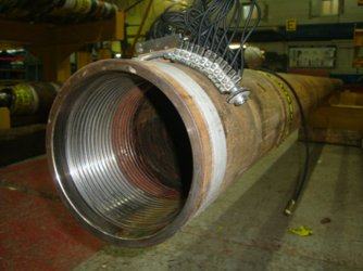
A batch of new stators was inspected using the MMM method at an oil wells drilling fabrication yard. The inspection was carried out by moving a scanning device connected to a TSC type (Tester of Stress Concentration) instrument along the external generating lines of the pipe (figure 1). If under such inspection pattern an abrupt local variation of the magnetic field was recorded in any place of the pipe along its length, then the additional inspection was carried out along the pipe perimeter. Figure 2 presents the magnetogram recorded during the inspection along generating lines with one of the new stator sides. The results of inspection by the MMM method, presented in figure 2, characterize satisfactory state of the new stator.
Figures 3, a and 3, b show the inspection results of another new stator with another works (serial) number. The inspection was carried out under a similar pattern. It can be seen in figure 3 that the magnetic field Hр and its gradient dH/dx display abrupt local variation in the female thread start area of the new stator. The polar magnetogram (figure 3, b) shows that there are abrupt local variations of the field in two diametrally opposite zones. According to the technique, these zones correspond to residual stress concentration zones (SCZ 1 and SCZ 2) formed during fabrication of this stator. Formation of annular cracks in SCZ 1 and SCZ 2 can be expected on this stator during its operation under load. These are exactly the stator areas where annular cracks on first turns of female thread are frequently detected during operation or preventive maintenance.
To prove the above stated, figure 4 shows the results of inspection by the MMM method of a used stator. It can be seen in figure 4 that an abrupt variation the magnetic field and its gradient is recorded in the crack initiation site.
Let us further consider the results of inspection by the MMM method of restrictors (limiters) used to change the cross-section and, accordingly, to change the flow rate of the moving medium inside the drilling rig. Figure 5 shows the general view of a restrictor; the direction of inspection by the MMM method is indicated with arrows on the restrictor casing. The casing also indicates the crack formed in the course of the restrictor operation.
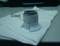
Figure 6 shows the scheme of inspection with the SD integrated in a special device. Turning of the restrictor by 360 degree around its axis provides recording of self-magnetic field distribution along the restrictor's perimeter in section coinciding with arrangement of the SD sensors.
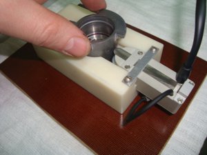
Figure 7 presents the results of new restrictors inspection by the MMM method. Figure 7, a shows the magnetogram recorded during the inspection along the perimeter in the bottom (fillet) part of the model No.6 restrictor. The SCZ recorded on this restrictor coincides with structural stress concentrator - the site of abrupt variation of the base shape. Figure 7, b shows the magnetogram recorded during the inspection in the bottom part of the model No.7 restrictor, which characterizes its satisfactory state.
Similar results of inspection by the MMM method were also obtained on other oil-production plant unit and components: fishing heads of oil well tubing, shafts of electric centrifugal pumps, etc.
Based on the results of inspection by the MMM method of the above-mentioned products for drilling rigs and oil-production plants a conclusion can be drawn that accelerated development of damages during operation occurs on units and components containing local SCZs due to metallurgical and process fabrication defects in condition as supplied (initial condition).
It is practically impossible to detect process and metallurgical defects located in the products metal depth using the applied common NDT methods. For example, if the task is to perform 100% inspection in the manual mode and during flow-line production of products using ultrasonic testing (UT), in this case a special guideline for operation in a search mode should be developed for an operator. However, even in this case, the operator should know where and how to install the UT sensor in order to try to detect an internal defect located at an unknown depth.
In automatic mode such inspection of products in on-line mode is even more impracticable.
The MMM method makes it possible in the quick control mode to record magnetic anomalies occurring on the products' surface in local RS zones that form due to internal defects of the metal. Additional inspection, for example, ultrasonic testing, may be performed in zones of magnetic anomalies (RS concentration zones). In this case, when the local RS zones is known, the UT operator knows where and how to install the sensor, and efficiency of a product's complex NDT increases considerably.
Conclusion
The presented in this paper application experience of the NDT technology based on the use of the magnetic memory of metal allows to state the possibility to perform 100% inspection of both new and used products in order to detect internal process and metallurgical defects.
Inspection using the MMM method requiring no preparatory operations can be automated on condition of development of specialized scanning devices that take into account structural features of products.
References
1. Nondestructive Testing and Diagnostics: Handbook / Edited by RAS academician V.V. Klyuev. Moscow: Machine building, 1995. 487 p.
2. Vlasov V.T., Dubov A.A. Physical bases of the metal magnetic memory method. Moscow: ZAO "TISSO", 2004. 424 p.
3. Dubov A.A., Dubov Al.A., Kolokolnikov S.M. Metal magnetic memory method and inspection instruments: Training handbook. Moscow: Publishing House Spektr, 2012. 395 p.