Diagnostics of rails, wheel pairs, locomotive parts and other products used in the railway transport
It was established that the main source of unexpected fatigue damages of rails, wheel pair tires, locomotive power parts and other products is presence of metal's internal stress concentration zones (SC zones) conditioned by the fabrication method. At present the rail- and wheel pairs manufacturing plants have no effective techniques and equipment for control of technological fabrication defects and residual stresses.
The conventional methods and equipment for field inspection (magnetic and ultrasonic flaw detectors) allow detecting the already developed defects. This inspection equipment does not provide the diagnostics of rails and wheel pairs at the pre-failure stage. Therefore they cannot guarantee safety of the railway traffic. The magnetic flaw detector cars, used during the field inspection, are based on reading of the magnetic leakage fields forming in the area of a developed defect location during the artificial magnetization of the rail with the static magnetic field.
There is an experience of the experimental rails inspection by the MMM method from the flaw detector car using the instrument-computer complex and sensors installed over the rail head (fig.1).
The performed work demonstrated the unique capabilities of the new diagnostic method: using two or four sensors, to carry out of the quick analysis of the rails' state and to determine the segments, susceptible to damaging, without special magnetization and the direct contact with the surface of inspection. Scanning may be performed at the locomotive traverse speed.
Fig.2 shows the fragment of the "manual" rail inspection using a specialized trolley. The abrupt local variation of the Hp magnetic field in the magnetogram corresponds to the area of the developing defect (cracks on the rail "head"). It should be noted that the SC line (Hp=0) indicates the direction of the detected crack propagation.
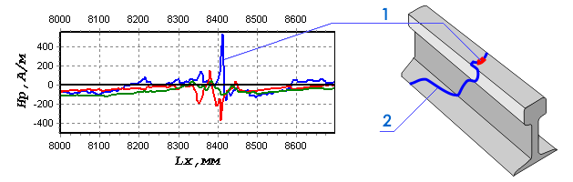
Fig.3 shows the results of a new rail inspection. The zone of residual stresses and metal defects concentration is characterized by the local Hp field variation (fig.3, a) and presence of the Hp field's sign alternation lines (fig.3, c). For the sake of comparison fig.3, b shows the magnetogram characterizing the satisfactory state of the new rail.
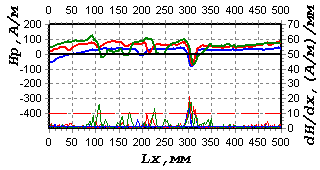
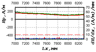
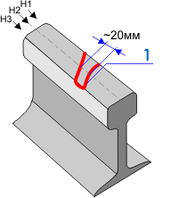
Fig.4 shows the inspection results of the locomotive wheel pair tires' stress-strain state using the metal magnetic memory effect. The specific criteria, by which the SC lines' depth can be judged and the cracks propagation can be predicted, are developed in special techniques.
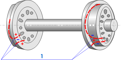
Fig.5 shows the inspection results of spiders used for torque transfer from the electric motor to the master drive unit of the electric locomotive wheel pair. The magnetogram in fig.5, b characterizes the high level of residual stresses - the source of damages development. The magnetogram in fig.5, c characterizes the residual state of the spider.
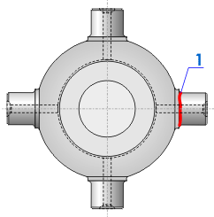
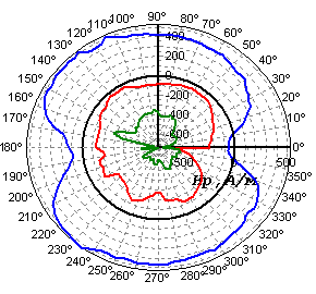
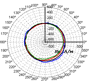
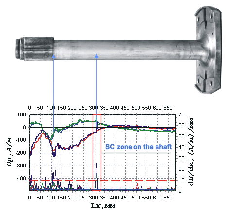
Fig.6 presents the fragment of the drive motor shaft inspection results. The areas of the abrupt local variation of the Hp field and its gradient correspond to the zones, in which the damages develop.