Diagnostics of steam turbine rotor flushing holes
Inspection was carried out using the TSC-type instrument and the Type 16 scanning device or the Type 5 sensor.
Fig.1 shows the example of the turbine rotor flushing hole using the Type 16 scanning device connected to the TSC-type instrument. Inspection was performed without metal dressing or any other preparation of the flushing hole surface.


Fig.1. The example of the turbine rotor flushing hole inspection using the Type 16 scanning device connected to the TSC-type instrument.
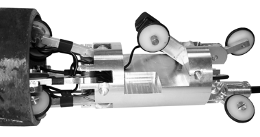
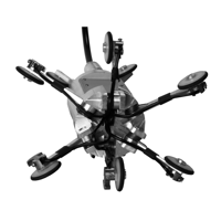
The Type 16 scanning device consists of a casing, in which a card for processing of signals from flux-gate transducers and length-metering impulses, float sensors unit and support wheels unit is installed. A plastic ⌀12mm tube is connected to the casing. The plastic tube is stiff enough to control the SD movement inside the inspected tube. A connecting cable to the TSC-type instrument is inserted inside the plastic tube. The internal diameter of the inspected tubes is within the range from 70 mm to 120 mm, the tubes length is up to 12 meters. The characteristic feature of this scanning device consists in its versatility in the indicated range of internal tube diameters. The scanning device has twelve flux-gate transducers in their two-component arrangement for simultaneous measurement of the normal and the tangential component components of the magnetic field.
Upon completing the magnetic inspection of the rotor flush hole the visual examination using endoscopes is carried out. Here the attention should be focused on the detected stress concentration zones. In case of defects detection in SC zones metal sampling is performed in these zones of the rotor flushing holes. Then the magnetic and visual inspection is repeated in order to assess the state of the flushing hole.